The Scout 100 and 140 can provide multiple Manual KPH (Keyphasor) Thresholds. These are nominally configured as: +3V, -3V, -8V, -13V, and -18V. It is possible that a valid small amplitude KPH signal within these limits will not cause the Scout to trigger.
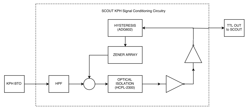
The purpose of this device is to convert a KPH signal to a signal that is compatible with the 3V manual threshold of the Scout 100 or 140. This device will be provided as a signal conditioner in-line with a Tachometer to KPH cable. This circuit is powered directly off of the Scout’s five volt power rail. It accepts a -24V Keyphasor as an input signal either directly from a Proximitor or from the monitor’s buffered transducer output. The output signal is 0-5 volt pulse that can be used to drive the Scout input directly.
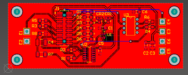
The prototype was built using a two layer, bare copper PWB fabricated with a CNC PWB router.
Features & Design Techniques
Converts a negative voltage pulse signal with unknown bias to a positive voltage, TTL compatible signal
- Low current device with a single +5Vdc source available
- Uses opto-isolator to setup a trigger/threshold and convert negative voltage to positive
- Uses Zener diodes to set threshold level
Hysteresis was implemented via hardware
- Implemented via a feedback loop on the opto-isolator
- Logic chip drives a CMOS switch to bypass or engage an additional diode which shifts the threshold level
Diode resistance was modeled to determine effects on frequency response.
Circuit Block Diagram
Specifications
| Amplitude | 0 to -24 V |
| Minimum trigger amplitude | 1.5 Vpp |
| Minimum Pulse Width | 100 µS |
| Minimum slew rate | 6 V/µs |
| Input | Notch |
| Duty cycle | ≥ 50% |
| Input Impedance | 20 kΩ ± 10% |
Responsibilities & Scope
- Circuit design and schematic capture in Altium
- Altium Designer PWB layout
- Tolerance analysis
- Assembly and testing
- Entire project from start to finish
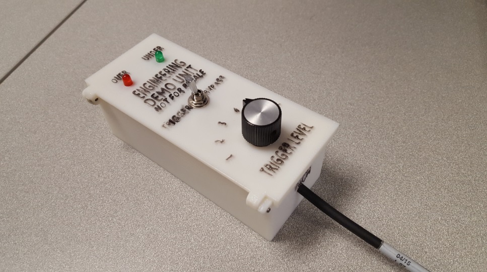
Project Photos
Comments are closed