This post covers part two of The Guide to Practical Operational Amplifiers. The topic for this post is a model covering how op amps operate in the real world and how that differs from the ideal op amp model.
Click here for the full Guide to Practical Operational Amplifiers.
The ideal op amp follows some basic “golden rules”. Ideal op amps have infinite open-loop gain. No current flows into the inputs, and the positive input terminal has the same voltage as the negative input terminal.
The ideal operational amplifier does not exist!
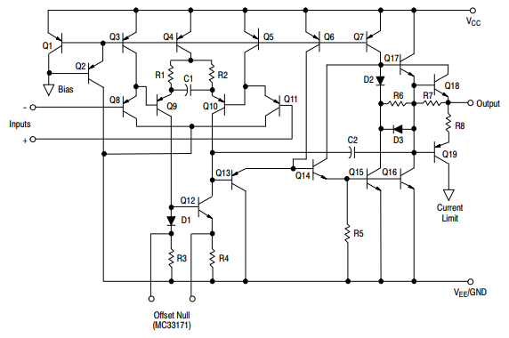
Practical op amps are real world devices primarily based on transistors but also have other internal circuitry. For example, the below figure shows a diagram of what is inside each op amp in the MC3317X series.
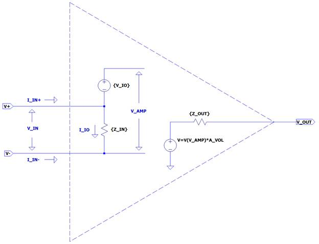
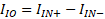
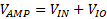
These non-ideal op amps have input currents and offsets, input and output impedance, limited gain, and other non-ideal properties. The next figure and the resulting equations describes the practical op amp model taking these effects into account.

This table compares these parameters with their ideal value. There will be upcoming posts covering non-ideal effects such as temperature, noise, slew rate, and stability.
| Parameter Name | Symbol | Ideal Value |
|---|---|---|
| Input Current | IIN | 0 Amps |
| Input Offset Current | IIO | 0 Amps |
| Input Offset Voltage | VIO | 0 Volts |
| Input Impedance | ZIN | ∞ Ω |
| Output Impedance | ZOUT | 0 Ω |
| Gain | AVOL | ∞ |
| Bandwidth | BW | ∞ Hz |
Comments are closed