Intro
I recently started to get back into high power rocketry. This project is an attempt to combine my electrical engineering experience and programming background with rocketry to create a real-time rocket tracker and telemetry system. An additional goal of this project is to make use of my amateur radio license. I was inspired to start this project after seeing a similar commercial system, the Missile Works RTx, in action.
Fundamentally, this project is a combination of a LightAPRS tracker and Missile Works RRC3 altimeter along with some custom software and firmware. The LightAPRS tracker provides a UART radio module, serial GPS receiver, and ATmega microprocessor in one Arduino compatible module. The selected altimeter has a UART telemetry stream.
The ultimate goal is to use this system with a Wildman Rocketry Darkstar 3 kit. I previously used a stock LightAPRS tracker in an upscale Cherokee model high power rocket. While the tracker functioned as designed, I believe the firmware can be improved upon for use in a rocket.
Note that this post was drafted in April of 2024 but not published until January of 2026.
Project Requirements
Functional Requirements
- Telemetry
- Provide real time altitude telemetry
- Provide real time speed telemetry
- Provide real time recovery deployment telemetry
- Transmit telemetry data via amateur radio
- Transmit rocket touchdown location
- Size
- Device should fit inside 3” dia. X 14” electronics bay
- Safety
- Device should be independent from altimeter deployment circuits
- Testability
- Device functionality should be able to be verified in the field without requiring a USB/serial connection and a terminal
Technical Requirements
- Altitude and speed telemetry data should be provided by an altimeter.
- Although anticipated rocket flights will be under GPS CoCoM altitude limits, they may exceed GPS CoCoM speed limits making GPS unavailable.
- Prior experience and research show that GPS data may be unreliable during the ascent portion of rocket flight. It is likely that the acceleration of the rocket during powered flight is higher than common hobby/commercial GPS modules can maintain GPS lock.
- Telemetry data should be provided via APRS protocol on the 2 meter amateur radio band
- I already have base station gear and the software stack necessary to receive signal
- I have prior experience with the APRS protocol
- Telemetry data should be transmitted via a LightAPRS transmitter
- I have prior experience with this transmitter
- This transmitter is based on the Arduino platform with open-source code that can be modified to meet these technical requirements
- Location data shall be transmitted with the telemetry data any time that GPS lock is available and location data is reported as valid.
- It is possible that the transmitter may leave visual line of sight and go over the horizon or a hill. Location data should be continuously transmitted as the rocket descends to assist in locating the rocket in case that signal reception is lost at or just before touchdown.
- Device shall share a rechargeable battery and power supply circuitry with the primary altimeter.
- A common ground will prevent differences in common mode voltage on the UART signal between the altimeter and the telemetry interface circuit.
- This is acceptable because the altimeter deployment circuits are not impacted, and there will be a redundant altimeter system with its own battery that is separate from this system.
- Device should transmit with 0.5 watts of power.
- The radio module on board the LightAPRS can be configured for either 0.5 or 1 watt transmit power. Using the lowest possible power is a tenet of responsible amateur radio operation.
- Device should transmit the status of the GPS signal and altimeter connection before launch.
- This will allow the user to verify the device is ready for launch.
The telemetry transmitter system block diagram is shown in the following figure. The heart of the system is the altimeter and LightAPRS tracker.
Transmitter Overview
LiPo Battery
The 2S LiPo rechargeable battery was selected for the following reasons.
Two LiPo cells in series (2S) provides approximately 7.4V. This falls within the valid input voltages of both the LightAPRS tracker and RRC3 altimeter. Furthermore, this voltage provides sufficient overhead for the LDO regulator on the LightAPRS.
The 1000 mAH capacity was selected to ensure that three launches can be made on a single battery charge. I made the assumption that 15 minutes would elapse between powering the LightAPRS, arming the altimeter, the rocket launching, and landing. Previous experience leads me to believe that this is sufficient time to achieve GPS lock, finish preparing the rocket for launch, inspection by a range safety officer, and launch. I also applied a safety factor of two since the primary altimeter is powered by the same battery, and the altimeter performs a safety critical function.
The following table shows the power budget calculations. Current draws were taken from the component datasheets, and the LightAPRS current draw assumes 0.5 watt transmit power. I made the conservative assumption that the RRC3 will provide it’s full rated 3 amps for 1 second for both the drogue parachute and main parachute. In reality this will be less. The e-matches used for deployment have a typical current draw of 1 amp and will fuse much faster than 1 second.
| Usage | Current [milliamps] | Duration [seconds] | Amp-Hours Required |
|---|---|---|---|
| RR3C | 35 | 900 | 0.00875 |
| Drogue Charge | 3000 | 1 | 0.00083 |
| Main Charge | 3000 | 1 | 0.00083 |
| LightAPRS | 500 | 900 | 0.12500 |
| Total | 0.13542 | ||
| x 3 flights | 0.40625 | ||
| x 2 safety margin | 0.81250 |
Missile Works RRC3 Altimeter
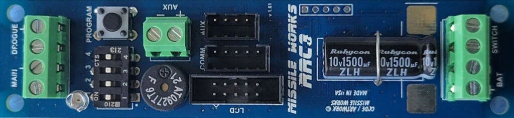
The Missile Works RRC3 altimeter was selected for it configurable telemetry options and operating voltage.
| Input Voltage | 3.5V – 10V | Compatible with 2S LiPo battery (7.4V) |
| Operating Voltage | 3.3V | Shares the same operating voltage as the LightAPRS. No logic voltage level translation required. |
RRC3 Telemetry Data
The RRC3 altimeter is configurable through the Missile Works mDACS software. The settings shown in the following table were applied. These settings configure the altimeter to provide the altitude in feet, speed in miles per hour, and deployment event status via the UART telemetry output every one half second starting once the altimeter powers up.
| Audio/LCD/Telemetry Units | English/Imperial Units (checked) Velocity Units Per Hour (checked) |
| Data Controls | Pre-Launch @ 0.5 sec. Rate |
| Data Items | Altitude, Velocity, Events |
The format of the telemetry UART data is: AAAAA,VVVV,DMA. Where AAAAA represents the altitude in feet, VVVV represents the speed in miles per hours, and DMA represents the deployment status. The drogue status is represented by D. The main parachute status is represented by M, and the auxiliary pyro channel is represented by A. Lowercase letters (dma) indicates continuity. Uppercase letters (DMA) indicates that the deployment event has taken place, and question marks (???) indicate no continuity. The output data format from the RRC3 altimeter is ASCII text and comma delimited with a <CR> character appended to the end of each line.
COMM Port Connector
The COMM port on the RRC3 altimeter uses the Hirose DF3 series connectors.
| Male PCB header | DF3A-5P-2DSA |
| In-line receptacle | DF3-5S-2C |
| Pre-crimped jumper wires | Digi-Key Link |
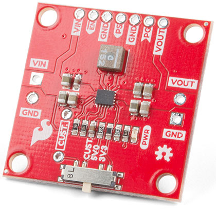
SparkFun Buck-Boost Converter
The LightAPRS input voltage specification according to the manufacturer is 4.5 V – 10 V when transmitting at 0.5 watt and 4.5 V – 8 V when transmitting at 1 watt. The manufacturer specifies a transmit interval of 60 seconds and cited overheating issues for the smaller input voltage range at the higher transmit power. I observed overheating issues in the LDO when transmitting at faster intervals (such as every few seconds) even at the 0.5 watt power setting. The SparkFun Buck-Boost Converter is necessary to prevent the LDO onboard the LightAPRS from overheating at the transmit intervals this project requires. This SparkFun breakout board is based on the Texas Instruments TPS63070 Buck-Boost converter and is configured for a 5 volt output.
The LDO onboard the LightAPRS appears to be the LD1117 voltage regulator in the SOT-223 package. According to the ST datasheet, the junction to ambient thermal resistance is 110°C/W. Since I did not design the LightAPRS and cannot be sure of the chip manufacturer or the copper layout underneath the LDO, this thermal resistance is an estimate. However, it the the best I have to go with. The amount of power the LDO has to dissipate can be calculated as follows.
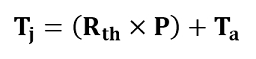
The following table is the result of calculating the LD1117 junction temperature for both 0.5 watt (460 mA) and 1 watt (760 mA) transmit power and a voltage input to the LightAPRS of 7.4 volts and 5 volts. This table shows that transmitting at 0.5 watt with a 5 volt power supply is the only combination investigated that prevents the LD1117 from exceeding its 125°C junction temperature rating.
| V_supply [volts] | 5 | 5 | 7.4 | 7.4 |
| I_load [amps] | 0.46 | 0.76 | 0.46 | 0.76 |
| P_D [watts] | 0.782 | 1.292 | 1.886 | 3.116 |
| T_J [°C junction] | 111.02 | 167.12 | 232.46 | 367.76 |
| T_A [°C ambient] | 25 | 25 | 25 | 25 |
| R_thJA [°C/W] | 110 | 110 | 110 | 110 |
Note that the above thermal calculation assumes a constant load. This was not the case for the stock LightAPRS. The manufacturer provided code transmitted only once per minute and turned off the radio module between transmissions. My custom firmware transmits at varying rates from just a couple seconds apart to fifteen seconds apart and does not turn the radio module off between transmissions.
RocketAPRS
RocketAPRS is the combination of the LightAPRS module and some custom firmware. LightAPRS is a commercial off the shelf APRS transmitter and is the heart of this project. It is based on an Atmega1284P-AU microcontroller, is Arduino compatible, and includes a radio transmitter, GPS antenna and module, and temperature/pressure sensor.
Full details of RocketAPRS can be found on my GitHub at github.com/imazel1303/RocketAPRS.
LightAPRS Custom Firmware
The LightAPRS is an Arduino compatible APRS tracker and is based on an Atmega1284P-AU microcontroller.
Available Pins
Various connections on the microcontroller are already used for the built-in functions to the LightAPRS such as managing the GPS and radio modules. Multiple other pins are not exposed for use by the LightAPRS end user.
| ATmega Pin # | ATmega Port |
|---|---|
| PB5 | Port B |
| PB6 | Port B |
| PB7 | Port B |
| PC0 | Port C |
| PC1 | Port C |
Port Description
Port B and Port C are 8-bit bi-directional I/O ports with internal pull-up resistors (selected for each bit). The Port B and Port C output buffers have symmetrical drive characteristics with both high sink and source capability. As inputs, Port B and Port C pins that are externally pulled low will source current if the pull-up resistors are activated. The Port B and Port C pins are tri-stated when a reset condition becomes active, even if the clock is not running. Port B and Port C pins can function as the source of external interrupts.
Pin Specifications
PB5
| Arduino Pin # | 5 |
| I/O Direction | Not set |
| Function | Not used |
PB6
| Arduino Pin # | 6 |
| I/O Direction | Input |
| Function | UART RX from Altimeter |
| Arduino Library | SoftwareSerial |
| Baud | 9,600 BPS |
| Data Bits | 8 |
| Parity | None |
| Stop Bit | 1 |
| V_high | 3.3 Vdc |
| V_low | 0 Vdc |
PB7
| Arduino Pin # | 7 |
| I/O Direction | Not set |
| Function | Not used |
PC0
| Arduino Pin # | 16 |
| I/O Direction | Not set |
| Function | Not used |
PC1
| Arduino Pin # | 17 |
| I/O Direction | Not set |
| Function | Not used |
Base Station Overview

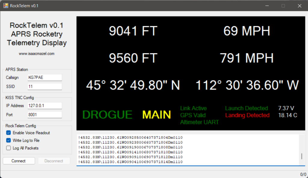
RockTelem
I wrote RockTelem as the real time display for high power rocket telemetry and location data transmitted from the RocketAPRS transmitter. It is written in C# and implements the KISS Protocol to interface with a TNC to display and log specially formatted APRS packets. In addition, this project includes a small library for extracting data from the KISS TNC APRS packet frame.
Full details of RockTelem can be found on my GitHub at github.com/imazel1303/RockTelem.
Features
- Real time display of RocketAPRS data
- Voice readout of altitude, deployment events, and maximum speed
- Connection to a networked TNC (compatible with Dire Wolf)
- Packet filtering based on amateur radio callsign and SSID
- Packet logging
- Test mode for replaying simulated flights
- Runs on Windows 10 and Windows 11
Electronics Bay
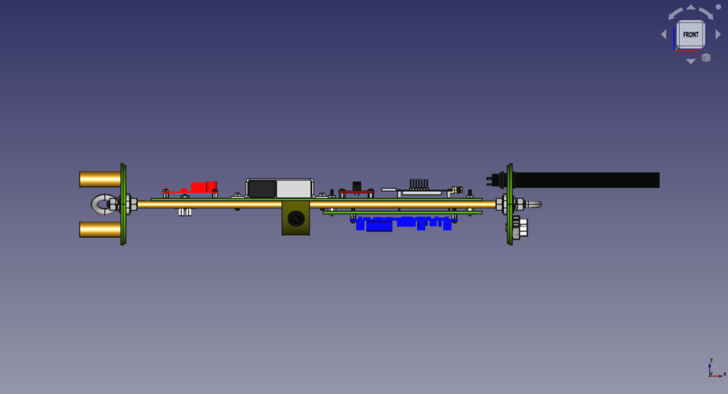
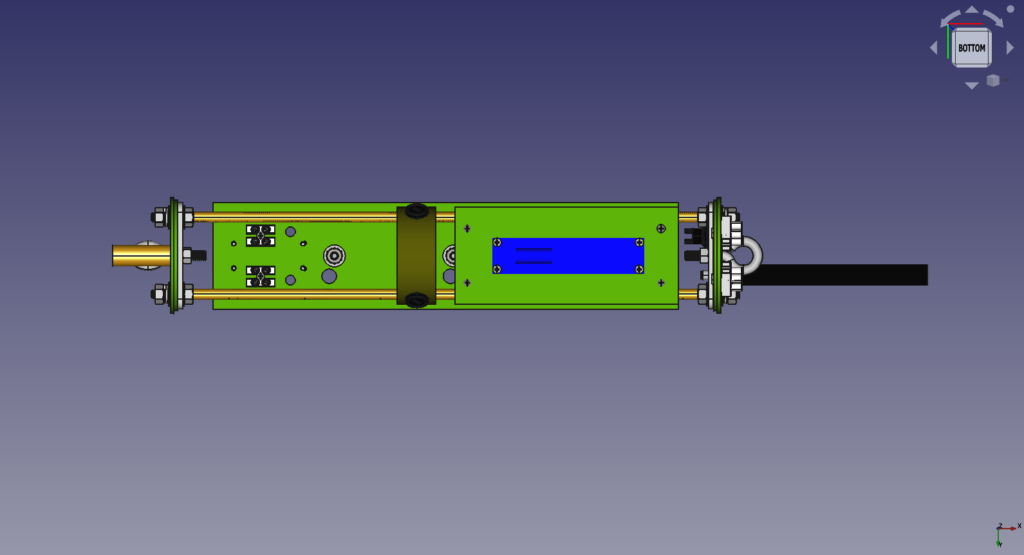
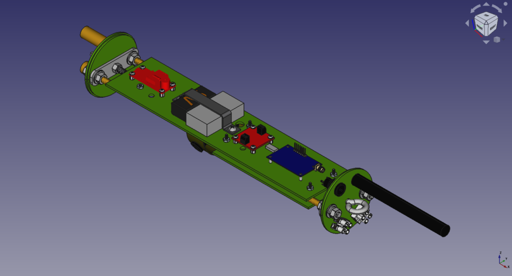
An electronics bay is needed to hold all of the above hardware in addition to the transmit antenna, backup altimeter system, power switches, various connectors, and charge wells. The Wildman Rocketry Darkstar 3 kit comes with a 3″ diameter by 9″ long coupler tube to build the electronics bay within. However, initial fit up of all the hardware indicated that it would not fit. I designed the electronics bay in FreeCAD. To fit all the hardware, I opted to purchase a 14″ long coupler tube. The electronics bay is completely self contained, and I included a switch band to allow this electronics bay to be swapped into different 3″ diameter rockets.
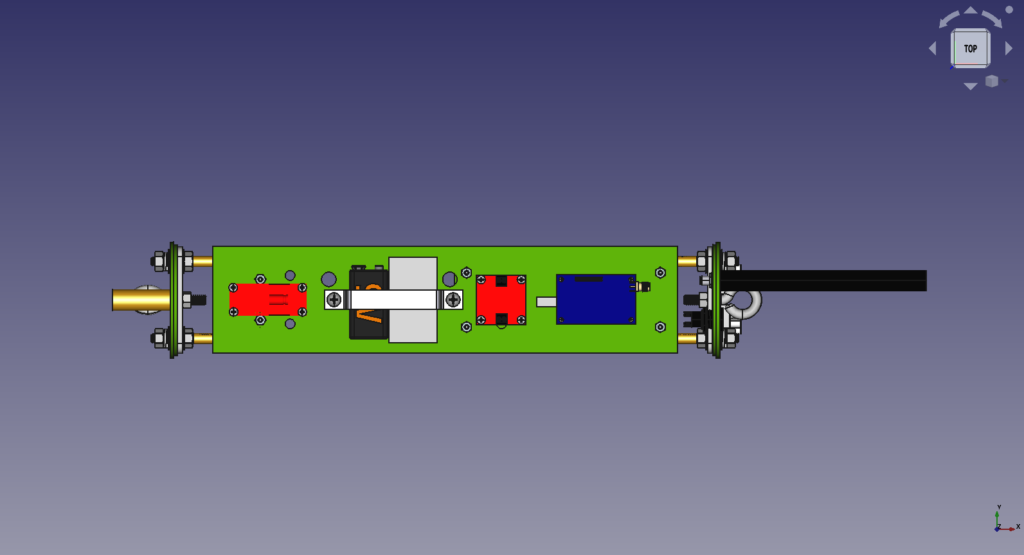

Two features of this design include the internal switch band fabricated out of Blue Tube as well as custom aluminum reinforcement brackets attached to the bulkheads. The internal switch band allows the power switch for the primary and secondary altimeter to be accessed via a small standard screwdriver from the outside of the rocket though the vent holes. There is an additional switch on the aft bulkhead to power the RocketAPRS tracker. The aluminum reinforcement bracket reinforces the two G10 fiberglass bulkheads and ensures that the fiberglass bulkheads do not solely bear the force of the two halves of the rocket separating.
Fabrication of the electronics bay was facilitated by using FreeCAD to create drill plans for the G10 fiberglass. Drill locations were transferred to the fiberglass by printing out the plans, laying them on top of the fiberglass, and then using a spring loaded center punch to mark the fiberglass through the paper at each drill location. PDFs of these drill plans are included with the CAD ZIP file.
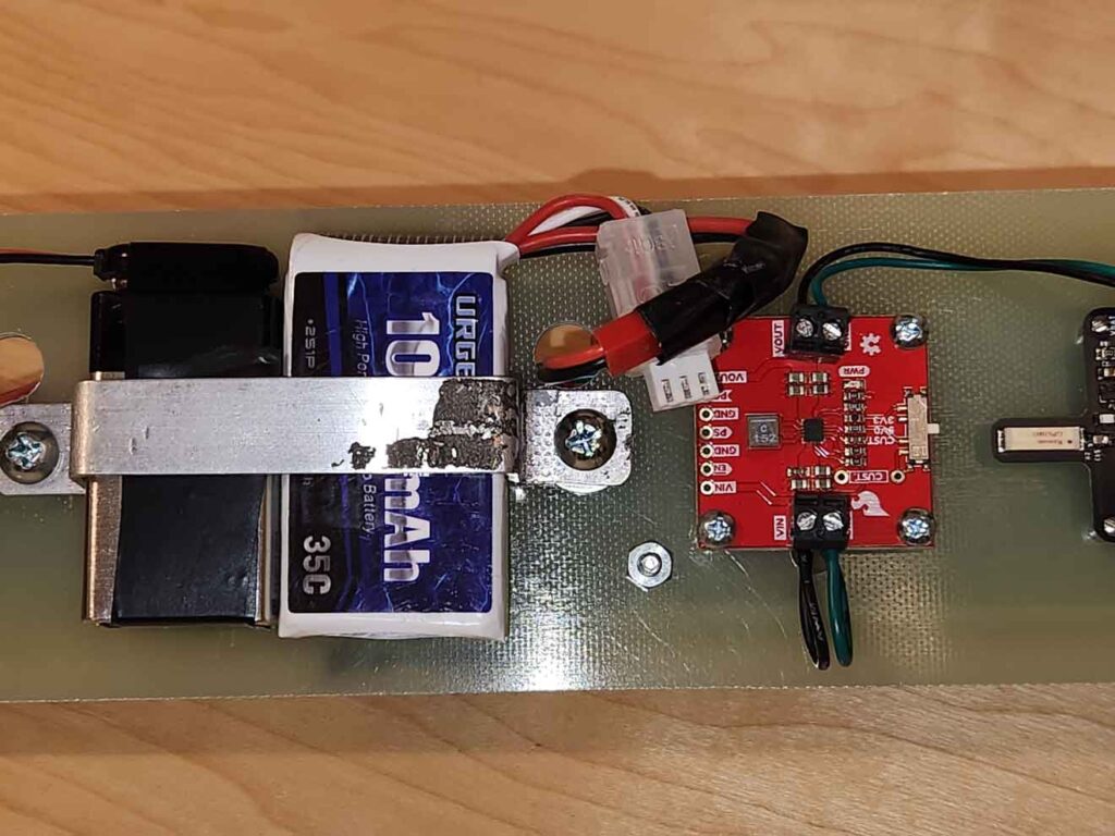
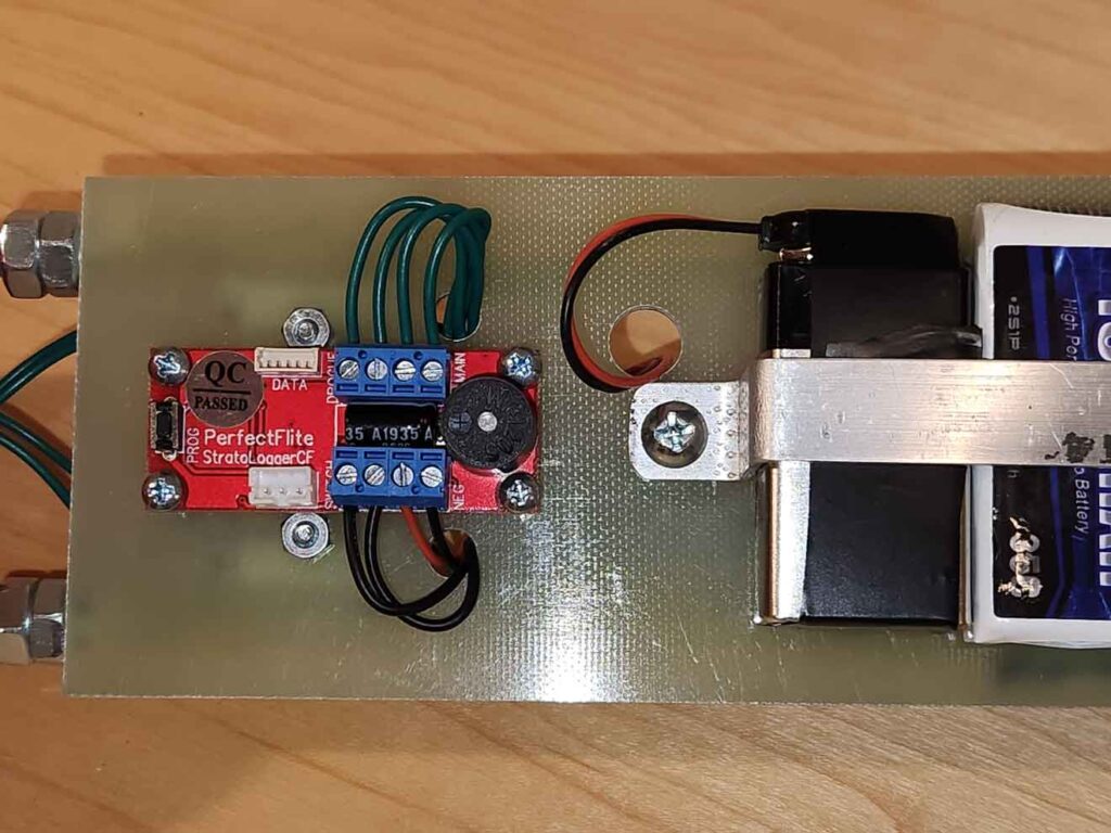
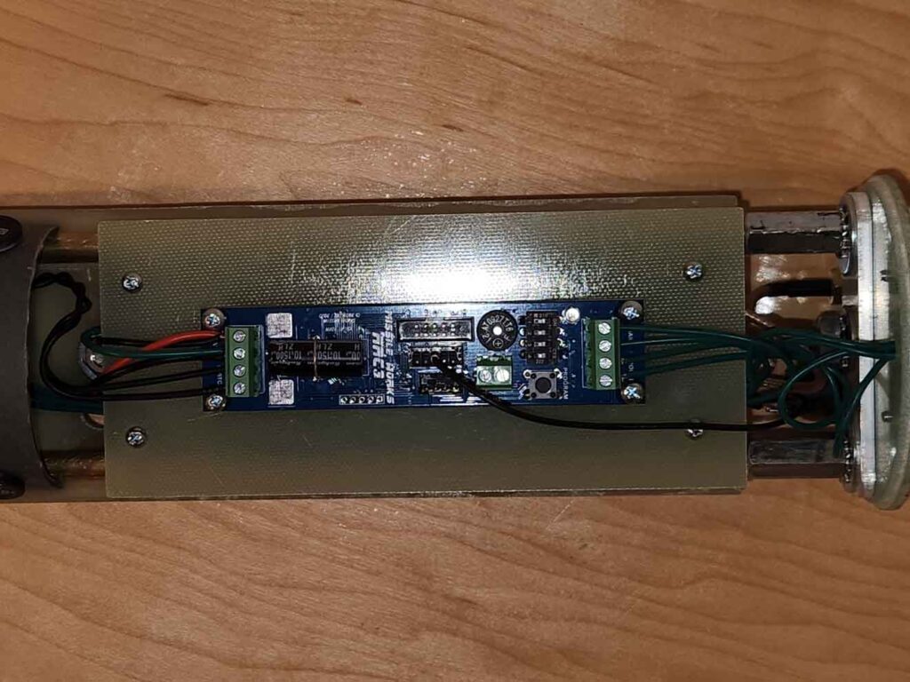
CAD Screenshots
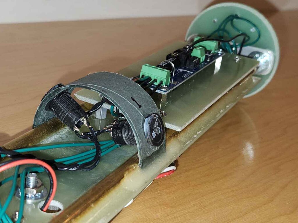
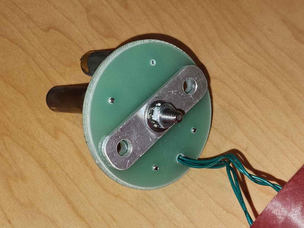
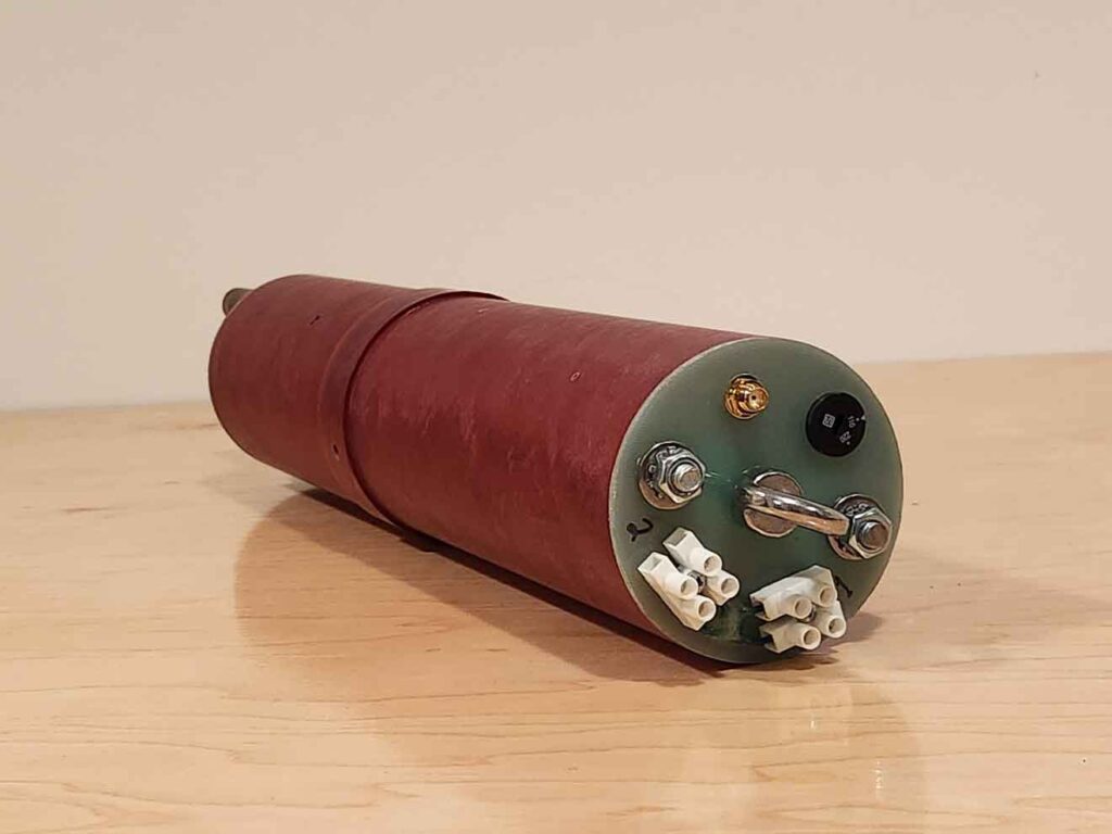
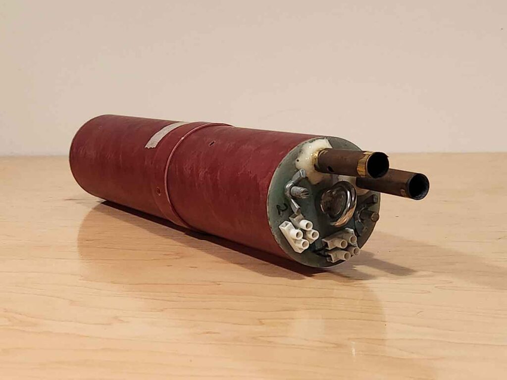
Build Photos
Results & Next Steps
To be continued…
Comments are closed